| 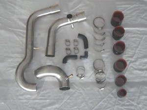 The
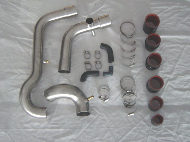
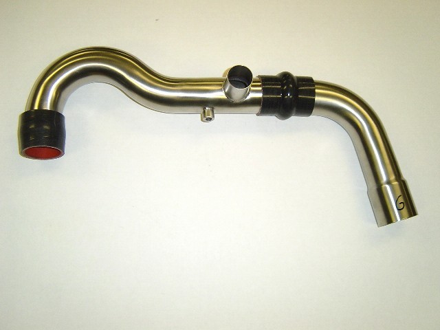
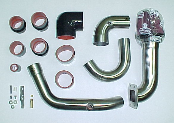
Intercooler pipes are made from 304 stainless steel with a beautiful
brushed finish. The Intercooler pipes are distinctly different. There
are six or seven silicone hoses and clamps depending on the turbo model
year. The hump hose has the bulge in it to allow more flexing from the
torque of the engine. Soapy water simplifies the installation of the
silicone hoses when sliding them onto the pipes, turbo and intake. To
protect the silicone hoses we specify only liner-type clamps that won't
tear the silicone surfaces and weaken the integrity of the silicone
hoses. If you need replacement clamps, contact Track Dog Racing. The
Intercooler pipes are made from 304 stainless steel with a beautiful
brushed finish. The Intercooler pipes are distinctly different. There
are six or seven silicone hoses and clamps depending on the turbo model
year. The hump hose has the bulge in it to allow more flexing from the
torque of the engine. Soapy water simplifies the installation of the
silicone hoses when sliding them onto the pipes, turbo and intake. To
protect the silicone hoses we specify only liner-type clamps that won't
tear the silicone surfaces and weaken the integrity of the silicone
hoses. If you need replacement clamps, contact Track Dog Racing.
11.1
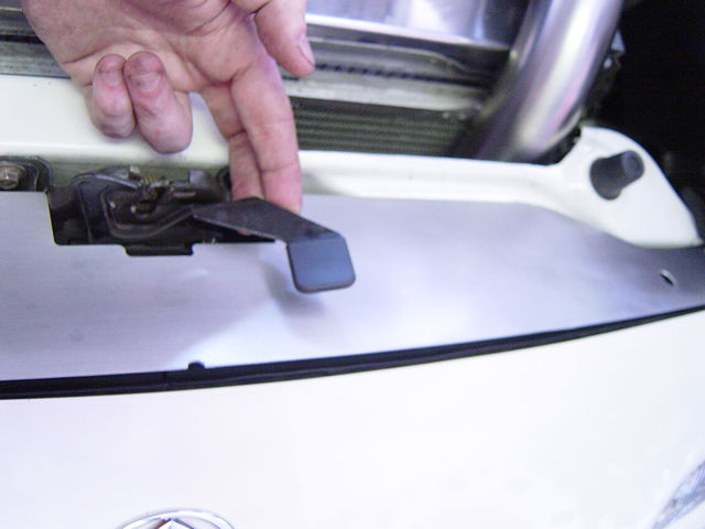
Installing The Lower Radiator Shield
- Lift up the hood
latch and slide the stainless steel panel, (brushed side
up) into place over the bolts on the two ends as shown in Photos 11-A
and 11-B.
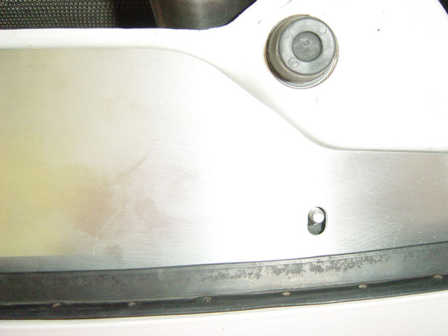
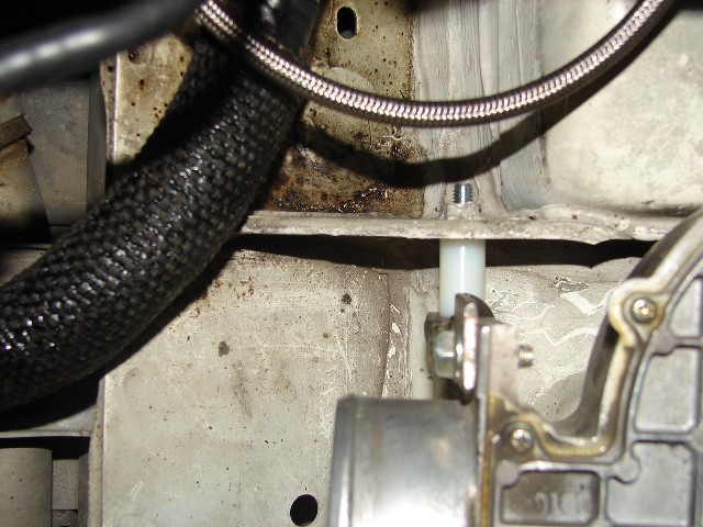
- Install the nylon nut
over the stainless steel panel. This nut holds the stainless
steel panel down and is also a spacer for the black aluminum radiator
panel as shown in Photo 11-C. Do not over-tighten; it takes
little effort to fasten securely.
11.2 Installing The Link
Temperature Sensor
Hardware Package
94FM for 94-97 Models
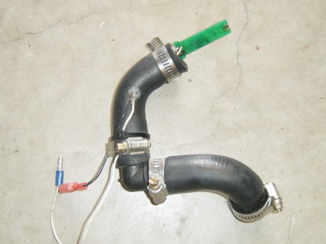
On turbo kits using the FM
Link temperature sensor you will need to assemble and modify the idle
air hose. On '90-93 model you can reuse the factory idle air hose.
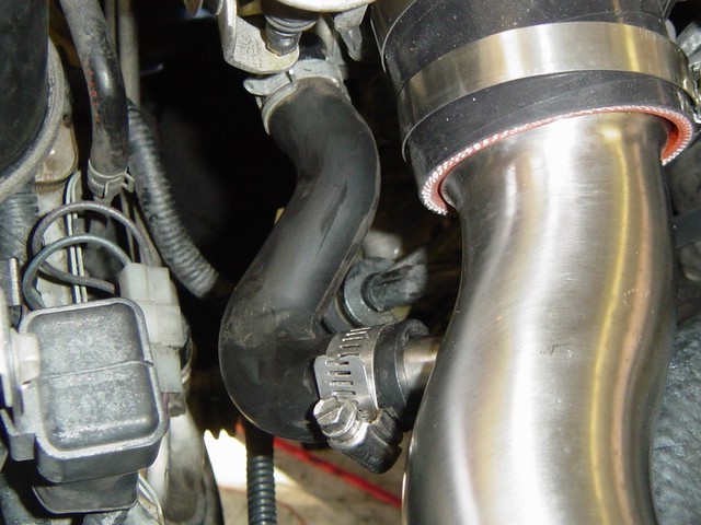
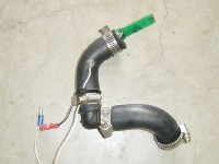
- On '90-93 models use
the factory hose and modify for the Link temperature sensor as shown
in Photo 11-D.
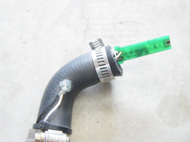
- Dry fit the hose configuration
before you modify the hose for the sensor wire exit. Use
soapy water on the hoses to help installation and simplify rotation.
Photos 11-E and 11-F show a typical mounting configuration.
- Cut a small hole
and pull the wires through. Use silicone to seal the wire
exit as shown in Photo 11-F. Try to penetrate the hole with the silicone
so it will have a good seal. Be sure to let the silicone seal dry
before you add boost.
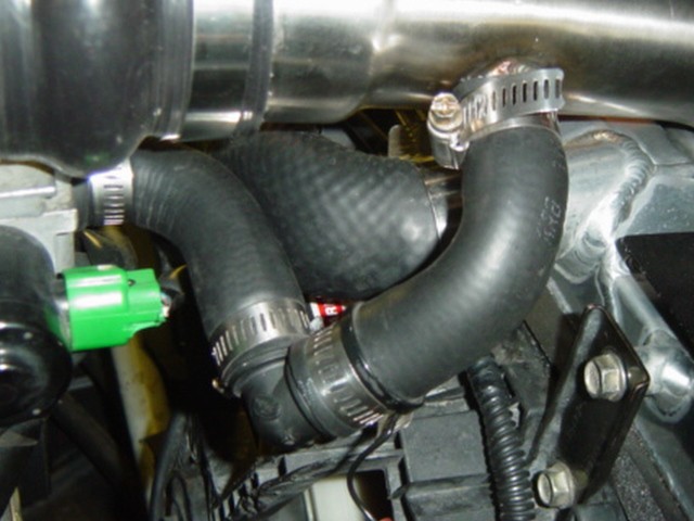
- Use the pipe clamps
provided
and install as shown in Photo 11-G.
 |
 |
 |
| Photo 11-D:
FM sensor hose kit '90-93 model |
Photo
11-E: FM sensor hose kit '94-97 model |
Photo 11-F:
Sensor wire seal |
 |
|
|
| Photo 11-G:
Sensor hose kit installed |
|
|
11.3 Installing The Intercooler
Pipes on the FM Turbo
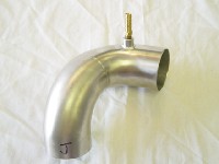
The '90-93 turbo model uses
a different intake pipe, but mounts similar to the '94-97 model. Because
of less clearances around the radiator hose the blow-off valve is attached
to the turbo outlet pipe. To make fitting of the silicone hoses to the
parts easier, spray a little soapy water onto the hose connection before
installing. The soapy water also acts as a sealant when it dries.
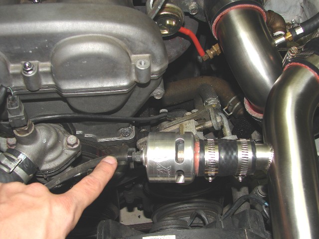
- There are two
brass fittings, both
using an 1/8" NPT thread. The 3/8" barbed end attaches
to the turbo inlet elbow as shown in Photo 11-H. The valve cover hose
connects to this fitting. If you are using a oil catch can, recommended,
use a plug (supplied) in place of the barbed fitting to seal off the
hole. The 1/8" barbed fitting attaches to the turbo outlet pipe
as shown in Photo 11-I. Some turbos come with a waste gate hose fitting
on the housing if so use a plug in place of the barb fitting. The
customer supplied waste gate hose connects to this fitting. Use Lock-Tit
on the thread to seal the barb or plug fittings.
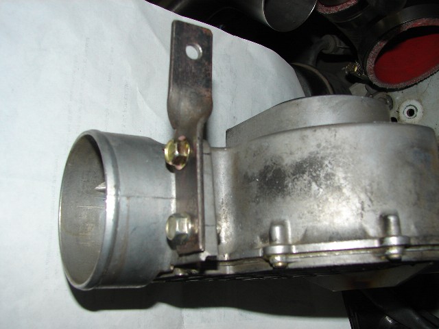
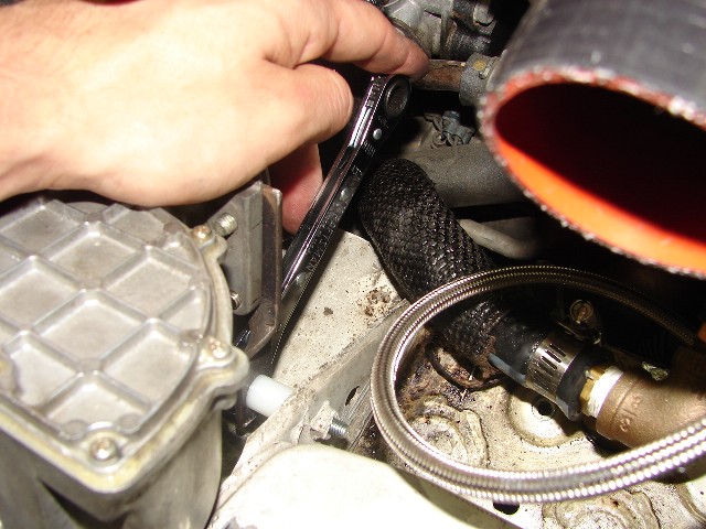
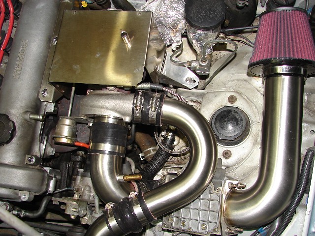
- To simplify installation
and removal of the connector hoses on the Intercooler, mount the
clamps so that the tightening bolt are on the front side as shown
in Photo 11-J. This will give you more clearance with a nut driver
(recommended for more torque) or screwdriver. To aid in a tight connection
use a ratchet with a 5/16" socket.
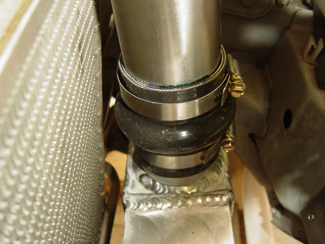
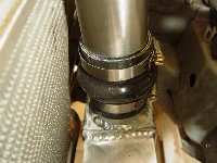
- Install the hump hoses
to the Intercooler using the medium size pipe clamps supplied as shown
in Photo 11-J. Slide the hose down so the bottom of the hump is at
the top of the Intercooler pipe. Ideally you want the Intercooler
pipe to mount just above the hump and the Intercooler to mount just
below the hump to allow flexing in between. Tighten the bottom clamp.
Place another clamp onto the top of the silicone hose in the same
direction.
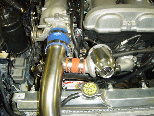
- Install the intake
pipe into the lower connector hose. Install the 2 1/2" silicone
connector hose on to the Intercooler pipe at the top as shown in Photo
11-L (Pictures are from the first prototype and are not the color
supplied). Use the larger clamps for mounting the top connector hose.
- Slide the connector
hose over the throttle body. Tighten only the clamp on the
throttle body securely. Tighten the clamp on the pipe lightly
so you can align the pipes. We will finish the alignment and tightening
in Section 11.5.
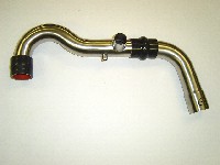
- Install the turbo
intake pipe using
a 2 1/2" to 2 1/4" transition silicone hose with a medium
size hose clamp on the turbo side and a larger clamp on the pipe side.
Position as need and install the customer supplied air filter.
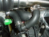
- On the '94-97
model install the turbo outlet pipe into the lower silicone
hose on the Intercooler. Take the 2" straight connector hose
and slide it on the Intercooler pipe at the turbo end. Use the medium
clamps for mounting the top connector hose as shown in Photo 11-M.
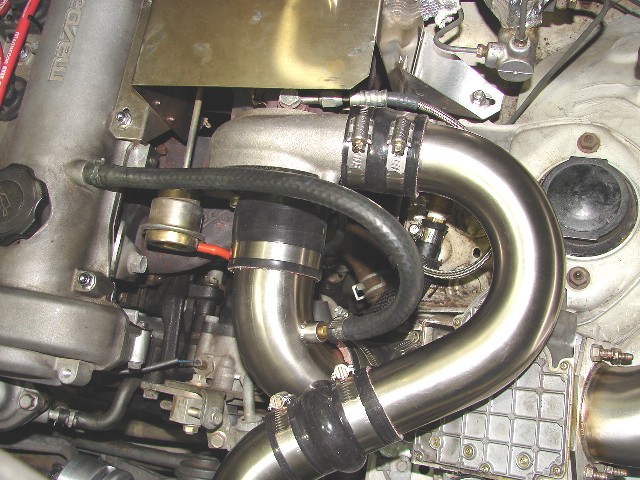
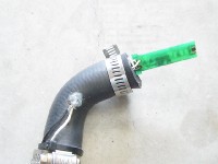
- On the '90-93
model their is a hump hose that goes on the turbo outlet pipe
to add additional length and flex to the pipe. Install the 2"
hump hose between the two pipes using the clamps supplied as shown
in Photo 11-N. Take the 2" straight connector hose and slide
it on the Intercooler pipe at the turbo end. Use the medium clamps
for mounting the top connector hose.
- Slide the connector
hose about halfway over the turbo outlet. Tighten only the
clamp on the turbo securely. Tighten the clamp on the pipe lightly
so you can align the pipes.
- Lightly tighten
both of the clamps on the Intercooler side of the pipes above
the hump hose. The bottom clamp on the hump hose should be securely
tightened.
| Click
on thumbnail image to see larger image in a new window
|
| 
|
 |
 |
| Photo
11-H: 3/8" barb fitting for valve cover hose |
Photo
11-I: 1/8" barb fitting for waste gate hose |
Photo
11-J: Install hump hose on to intercooler |
 |
 |
 |
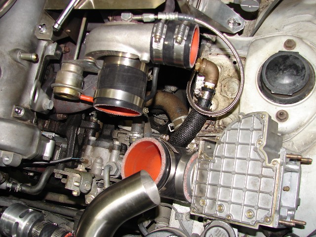
| Photo
11-K: Rotate I/C pipe into position, check clearances |
Photo
11-L: Intake side with customer supplied BOV |
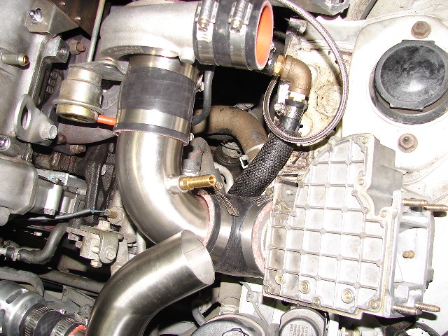
Photo
11-M: Turbo Inlet and outlet pipes |
 |
|
|
| Photo
11-N: '90-93 turbo outlet pipe with silicone fittings |
|
|
|
11.4 Installing
The Intercooler Pipes on the Greddy Turbo
The Greddy setup comes with 4 pipes on the turbo side and 1 pipe
for the intake side. To
make fitting of the silicone hoses to the parts easier, spray
a little soapy water onto the hose connection before installing.
The soapy water also acts as a sealant when it dries.
Hardware Package
- Greddy
- Install
the 3/8" brass barb fitting
into the turbo intake pipe as shown in Photo 11-W.The valve
cover hose connects to this fitting. If you are using a oil
catch can, recommended, use a plug (supplied) in place of the
barbed fitting to seal off the hole. Use Lock-Tit on the thread
to seal the barb or plug fitting.
- To simplify installation
and removal of the connector hoses on the Intercooler, mount
the clamps so that the tightening bolt are on the front side
as shown in Photo 11-P. This will give you more clearance with
a nut driver (recommended for more torque) or screwdriver. To
aid in a tight connection use a ratchet with a 5/16" socket.
- Install the hump
hoses to the Intercooler using the medium size pipe clamps
supplied as shown in Photo 11-P. Slide the hose down so the
bottom of the hump is at the top of the Intercooler pipe.
Ideally you want the Intercooler pipe to mount just above the
hump and the Intercooler to mount just below the hump to allow
flexing in between. Tighten the bottom clamp. Place another
clamp onto the top of the silicone hose in the same direction.
- Install the intake
pipe into the lower connector hose. Install the 2 1/2"
silicone connector hose on to the Intercooler pipe at the top
as shown in Photo 11-Q. Use the larger clamps for mounting the
top connector hose.
- Slide the
connector hose over the throttle body. Tighten only
the clamp on the throttle body securely. Tighten the clamp on
the pipe lightly so you can align the pipes. We will
finish the alignment and tightening in Section 11.5.
- Use the
factory idle air hose as shown in Photo 11-Q and modify
as required.
- Install
the supplied mounting bracket to the airflow unit as
shown in Photo 11-S using the supplied 12.5 mm bolts and washers.
Mount on the outside of the airflow bracket.
- Using the
two 1/2" nylon spacers and supplied bolt attach
the airflow and bracket to the shock tower support as shown
in Photo 11-T. Tighten down to the point you can still move
the airflow unit for alignment.
- Install
the 2 3/4" silicone 90 deg. hose to the airflow
unit with a clamp. Loosely tighten the clamp until all adjustments
are complete.
- Slide on
a 2 1/2" silicone hose with clamps over the 90
deg. turbo intake pipe with a little bit of soapy water. Add
some soapy water to the 2 3/4" silicone fitting as well.
Insert the pipe as shown in Photo 11-W. Adjust as necessary
and lightly tighten until complete.
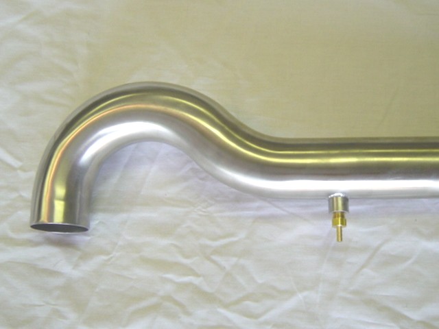
- Using the
factory nuts on the airflow unit install the new 2
3/4" air filter pipe as shown in Photo 11-X. Install the
new air filter to the pipe and tighten down.
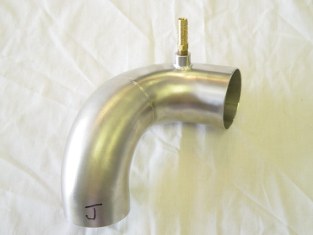
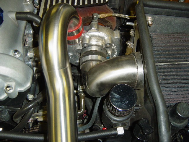
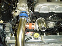
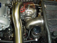
- The turbo
outlet pipes consist of two parts, either one can be
installed first. Attach the supplied 2" straight silicone
hose with clamps to the turbo outlet. Attach the curved pipe
on to the turbo outlet as shown in Photo 11-Y.
NOTE: The turbo may
require you to rotate it some to align the Intercooler pipes properly.
Usually you can twist the turbo by hand for this adjustment, but
you may require a rubber mallet or other soft material to aid
in the movement.
- Attach the
2" silicone hump hose to the other end of the
curved pipe. Use soapy water to help aid the fitting.
- Attach the
other turbo outlet pipe to the Intercooler and to the
curved pipe as shown in Photo 11-Y. Be sure to leave at least
a 1/4" gap between these two pipes or about the distance
of the hump section of the silicone hose. Tighten loosely until
ready to align. See Section 11.5 on aligning the Intercooler
pipes.
- Install
customer supplied BOV using supplied silicone hose
and clamps as shown in Photo 11-Z. Attach a vacuum hose to the
intake manifold.
11.5
Installing The Radiator Shield And Aligning The Intercooler
Pipes
This next step is for
all intercooler models.
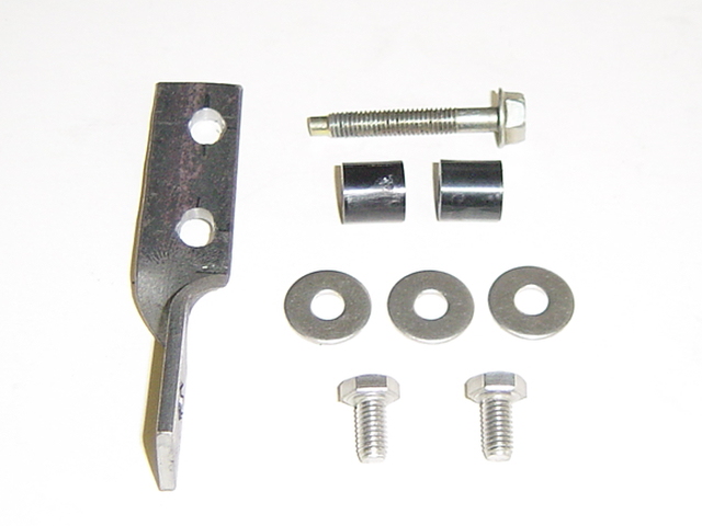
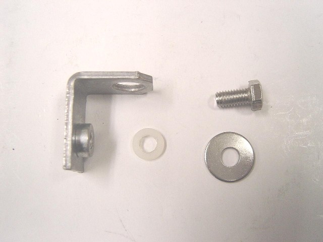
Hardware
Package A-1
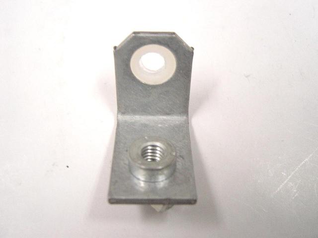
- Locate the
L bracket and hardware from package A-1 as shown in
Photo 11-AA.
- Insert the
nylon spacer into the L bracket as shown in Photo 11-BB,
if it is not already installed.
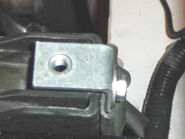
- Remove the
10mm bolt from the top of the radiator bracket and
install the L bracket using the supplied 10 x 12.5mm bolt and
washer as shown in Photo 11-CC.
- Mount the black
aluminum radiator shield over the pipes and to the 4 studs.
It is not necessary to install the acorn nuts while aligning.
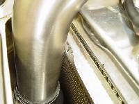
- Check the
fit between the shield and the Intercooler pipes
to make sure the Intercooler pipes have good clearance and are
not making contact with the shield or the frame area as shown
in Photo 11-DD. If you can see any frame area as shown in Photo
11-DD through the pipe opening, remove the metal. Take caution
to not get any metal shavings into the Intercooler.
- To allow
flexing, try to keep a minimum of 1/4" of space
between the pipe and the shield.
- Hood clearance
is close on the turbo side. Start by pressing the pipe down
into the intercooler and feel for about a 1/4" of space
where the pipe and the intercooler meet. Align the pipe to have
good air gap around the shield as shown in Photo 11-DD and then
tighten the top clamp. The top clamp will hold the pipe in alignment.
Use a nut driver for more torque.
- Align and
tighten down the intake side using the same method
and keeping a good air gap as shown in Photo 11-EE.
- Remove the aluminum
radiator shield and without moving the pipes securely tighten
the lower Intercooler hose clamps.
- Check the
radiator shield again and retighten all of the hose
clamps.
- Securely tighten
the aluminum radiator shield using the stainless steel washer
and acorn nuts supplied from package A-1.
- You should
have good hood clearance and air gap around the radiator
shield if done properly, but you might want to do a hood clearance
check as shown below in Section 11-6.
11-6 Checking For Clearance On The Intercooler Pipes
Hood clearance may
or may not be an issue, but it would not hurt to check. If you
have stock motor mounts you will have excess engine movement that
WILL cause the pipes to touch the hood. Be sure to replace the
motor mounts with our Mazda Speed heavy-duty motor mounts, as
they will reduce engine movement.
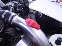
- Photos below
show how to check for hood clearance. Play-Do is inexpensive
and available from grocery stores, drug stores and department
stores for about $2.00.
- Place the
Play-Do on the pipes and close the hood all the way
as shown in Photo 11-GG.
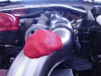
- Look were
the hood presses into the the Play-Do as shown in Photo
11-HH. The hood brace makes contact with the Play-Do.
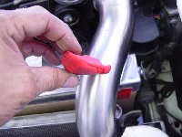
- Carefully
pull the Play-Do off the pipe and look at the thickness.
Ideally we would like to see a minimum of a 1/4" as shown
in Photo 11-JJ. Keep in mind as the engine torques toward the
passenger side the pipes will move out from under the hood brace.
- If necessary,
re-adjust the pipes for more hood clearance as shown
in Section 11.4.
|
| Click
on thumbnail image to see larger image in a new window
|
 |
 |
 |
| Photo
11-GG: Play-Do on pipe to check hood clearance |
Photo
11-HH: Look were the hood presses into the Play-Do |
Photo
11-JJ: Check thickness of Play-Do |
|