|
3.1
Cross Member Modification
The front cross
member has to be trimmed to allow access to the Intercooler. The measurements
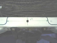
drawn in Photo 3-A below shows the area that needs to be cut.
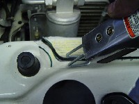
The best tool to use is an air-operated reciprocating saw as shown
in Photo 3-B, but an electric jig saw will work as well. This
cut will be covered up by the aluminum radiator shield that will be
installed later. Mark the area using a Sharpie or other
ink pen and double-check all dimensions before cutting.
- Apply masking tape
to the working area to avoid scratching the painted surface.
- Photo 3-A shows
the dimensions for the center non-cut area. There is a
hole in the center that will be your measuring mark. Mark 3 1/8"
from the center make on both sides as shown in Photo 3-A. The cut
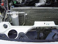
is going to be at the cusp of the bend of sheet metal shown in Photo
3-C.
- Draw
a radius line equal to the rubber hood stand-off
about 1/2" out on the right side as shown in Photo 3-B. On
the left side (drivers side) draw a similar line at the base of
the rubber hood stand-off as this side requires more clearance.
Once you install the intercooler pipes some additional cutting may
be required as shown in Photo 3-E.
- Using a pilot bit
first and then a 3/8" drill bit, drill two holes on each
corner where you will have a radius as shown in Photo 3-C. This
will help with access for the saw in the turns and improve the appearance
of the cut. If you are using a narrow saw blade you may not need
these pilot holes as your saw will allow tight radius bends.
- Using the jig saw
or air-operated saw with a metal cutting blade, cut across the
front cross member.
- It is important
that you take a flat file or your Dremel Tool and round off
the edges and corners so you don't cut your hands or arms when working
in this area. Make sure you clean these areas of metal chips since
you would not want them to fall into your Intercooler during installation.
- Additional cutting,
particularly on the driver's side, may be required as shown
in Photo 3-E after the intercooler is mounted and the pipes are
being installed. Be sure to use masking tape again to protect the
paint when cutting.
- Use some factory
touch-up paint on the cut edge.
Click on thumbnail
image to see larger image in a new window
 |
 |
 |
| Photo
3-A: Mark at 6 1/4" outside for cut-out |
Photo
3-B: Use a reciprocating saw to cut out |
Photo
3-C: Left side cut out |
 |
 |
 |
|
Photo 3-D: Right side cut out |
Photo 3-E: Additional cutting may be required |
Photo
3-F: Remove sharp edges |
3.2
Stainless Steel Cover Hardware Installation
The stainless
steel cover hardware is attached.
Hardware
Package A-1
- Remove the 10mm bolts
on top between the rubber hood stopper and the front bumper
as shown in Photo 3-G on both sides of the front area.
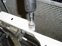
- Screw in from
the bottom a 10 x 35mm long bolt with threads on top as
shown in Photo 3-H. Install the supplied nylon nut (steel nut shown).
This nut is used as a spacer for the new stainless steel panel.
Click
on thumbnail image to see larger image in a new window |