|
 The
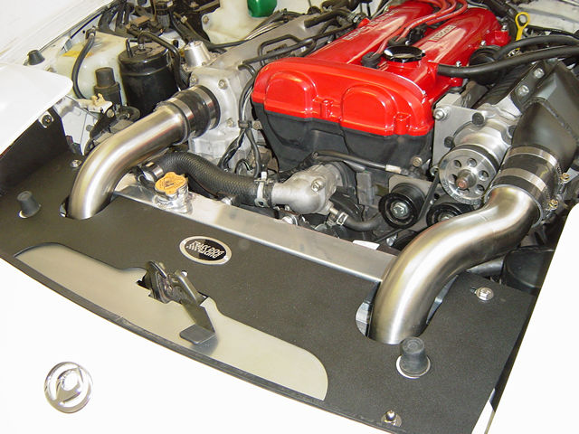
Intercooler pipes are made from 304 stainless steel with a beautiful
brushed finish. The two Intercooler pipes are distinctly different.
The supercharger side pipe has more bends than the intake side pipe
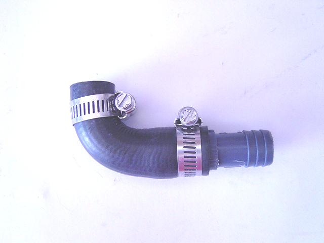
as shown in the photo to the right. There are four silicone hoses and
clamps. The hump hose has the bulge in it to allow more flexing from
the torque of the engine. The hump hoses use the smaller clamps for
mounting and attaching to the Intercooler. The other two transitional
silicone hoses mount on the engine side. Soapy water simplifies
the installation of the silicone hoses when sliding them onto the pipes,
the dummy throttle body and supercharger outlet. To protect the silicone
hoses we specify only liner-type clamps that won't tear the silicone
surfaces and weaken the integrity of the silicone hoses. The
Intercooler pipes are made from 304 stainless steel with a beautiful
brushed finish. The two Intercooler pipes are distinctly different.
The supercharger side pipe has more bends than the intake side pipe
as shown in the photo to the right. There are four silicone hoses and
clamps. The hump hose has the bulge in it to allow more flexing from
the torque of the engine. The hump hoses use the smaller clamps for
mounting and attaching to the Intercooler. The other two transitional
silicone hoses mount on the engine side. Soapy water simplifies
the installation of the silicone hoses when sliding them onto the pipes,
the dummy throttle body and supercharger outlet. To protect the silicone
hoses we specify only liner-type clamps that won't tear the silicone
surfaces and weaken the integrity of the silicone hoses.
11.1
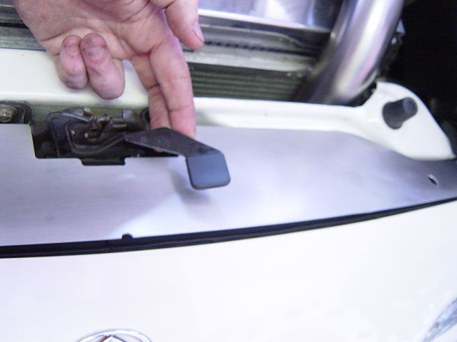
Installing The Lower Radiator Shield
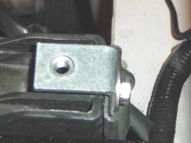
- Lift up the hood
latch and slide the stainless steel panel, (brushed side
up) into place over the bolts on the two ends as shown in Photos 11-A
and 11-B.
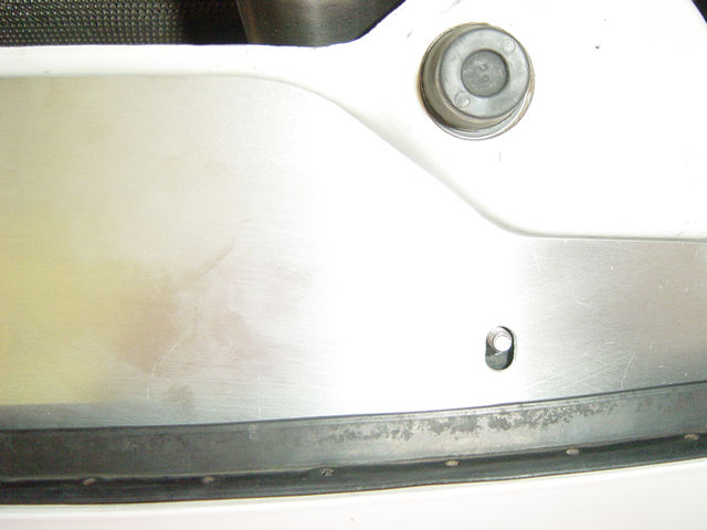
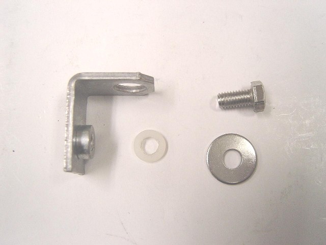
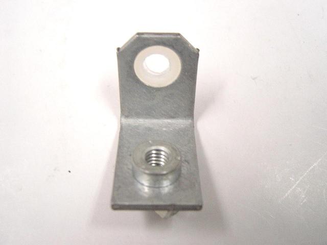
- Install the nylon nut
over the stainless steel panel. This nut holds the stainless
steel panel down and is also a spacer for the black aluminum radiator
panel as shown in Photo 11-C. Do not over-tighten; it takes
little effort to fasten securely.
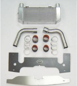
11-2 Installing The Intercooler
Pipes
Hardware Package
F
To make fitting of the silicone
hoses to the parts easier, spray a little soapy water onto the hose
connection before installing. The soapy water also acts as a sealant
when it dries. Installation is similar for all model years.
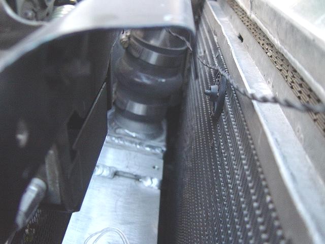
- To simplify installation
and removal of the connector hoses on the Intercooler, mount the
clamps so that the tightening bolt are on the front side as shown
in Photo 11-E. This will give you more clearance with a nut driver
(recommended for more torque) or screwdriver.
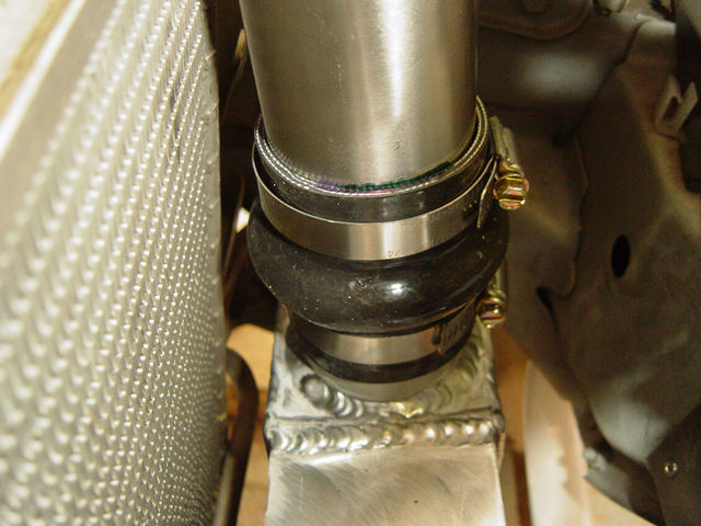
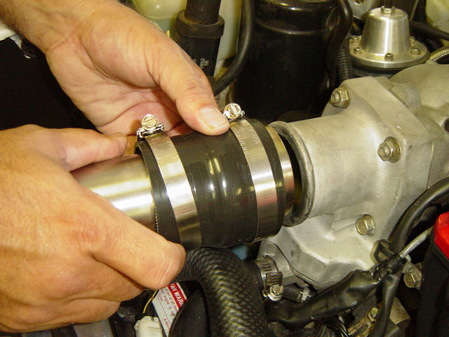
- Install the hump hoses
to the Intercooler using the smaller of the two pipe clamps supplied
in Package F as shown in Photo 11-D. Slide the hose down so the bottom
of the hump is at the top of the Intercooler pipe. Ideally you
want the top Intercooler pipe to mount just above the hump to allow
flexing in between. Tighten the bottom clamp. Place another clamp
onto the top of the silicone hose in the same direction.
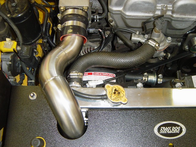
- Install the intake
pipe into the lower connector hose. Take the 2 3/4" to 2
1/2" transition silicone connector hose and slide it on to the
Intercooler pipe at the top as shown in Photo 11-D. Use the larger
clamps for mounting the top connector hose. We prefer the clamp tightening
bolt to be on the outside.
- Slide the connector
hose about halfway over the dummy throttle body. Tighten
only the clamp on the throttle body securely. Tighten the clamp on
the pipe lightly so you can align the pipes. Photo 11-I shows
the 90-93 intake pipe installation.
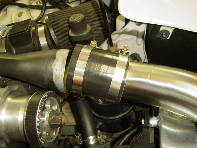
- Install the supercharger
pipe into the lower silicone hose on the Intercooler. Take
the 2 1/2" straight connector hose and slide it on the Intercooler
pipe at the top. Use the larger clamps for mounting the top connector
hose as shown in Photo 11-H.
- Slide the connector
hose about halfway over the supercharger. Tighten only the
clamp on the supercharger securely. Tighten the clamp on the pipe
lightly so you can align the pipes.
- Tighten both of
the lower connector top clamps lightly. The bottom clamp
on the hump hose should be tightened securely.
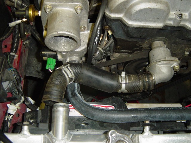
- To improve the
idle air hose location the 94 and newer supercharger dummy
throttle body fitting may extend straight out as shown in Photo 11-J.
Installing the 90 deg. fitting can simplify the hose arrangement by
lowering the hose between the radiator and the engine. Install the
idle air hose 90 deg. adapter from Package I-1 to your existing 3/4"
rubber hose, as shown in Photo 11-K.
|