|
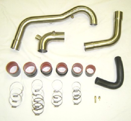
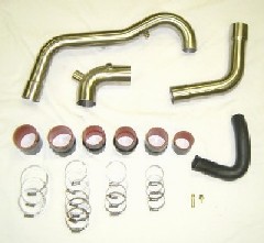
The Intercooler pipes are made from
304 stainless steel with a beautiful brushed finish. For the turbo cars
there are two distinctly different intercooler pipe setups depending
on your aftermarket turbo setup. To protect the silicone hoses we specify
only liner-type clamps that won't tear the silicone surfaces and weaken
their integrity. Please contact TDR if you need a replacement. Standard
hose clamps will destroy the silicone hoses.
11-1 Installing the FM
System Intake Side Intercooler Pipes
 The
FM turbo Intercooler kit comes complete with the turbo outlet
pipe, turbo inlet pipe and the intake pipe. The FM air filter and air
box are retained. The
FM turbo Intercooler kit comes complete with the turbo outlet
pipe, turbo inlet pipe and the intake pipe. The FM air filter and air
box are retained.
To make fitting of the silicone
hoses to the parts easier, spray a little soapy water onto the hose
connection before installing. The soapy water also acts as a sealant
when it dries.
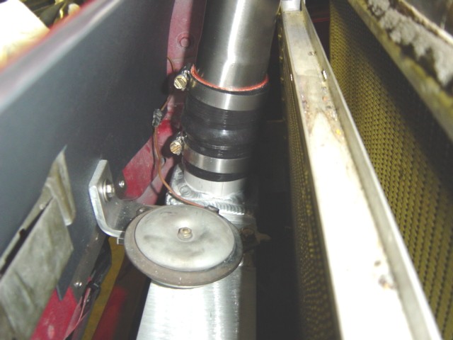
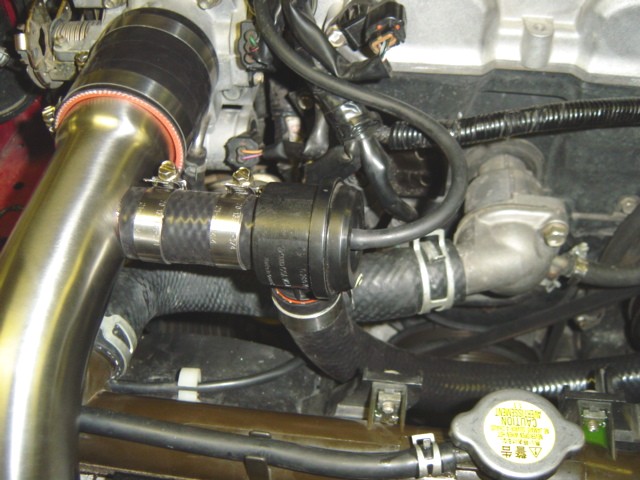
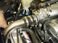
- To simplify installation
and removal of the silicone hoses on the Intercooler, mount the
clamps so that the tightening screw is on the front side, as shown
in Photo 11-A. This will give you more clearance with a nut driver
(recommended for more torque) or screwdriver.
- Install the hump hoses
onto the Intercooler using the smaller size hose clamps as shown in
Photo 11-A. Slide the hose down so that the bottom of the hump is
at the top of the Intercooler pipe. Ideally you want the top
Intercooler pipe to mount just above the hump to allow flexing in
between. Tighten the bottom clamp secure. Place another clamp onto
the top of the silicone hose. Photo 11-A also shows placement of the
factory horn mounted to the top of the intercooler.
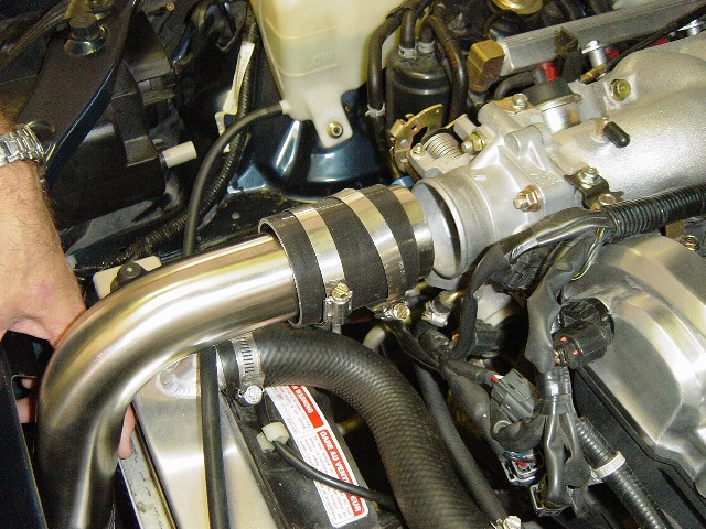
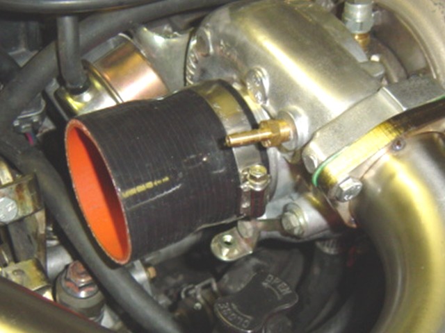
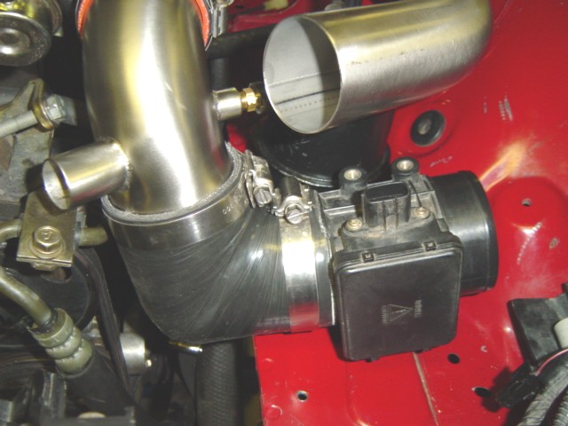
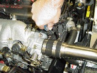
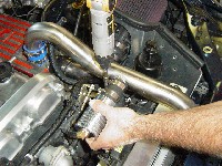
- Install the intake
pipe into the lower connector hose. Take the 2 1/2" silicone
hose and slide it on to the Intercooler pipe at the top as shown in
Photo 11-B.
- Place two larger clamps
onto the pipe with the tightening screws toward the inside, as
shown in Photo 11-B. Holding the assembly, rotate the intercooler
pipe toward the throttle body and line up as shown.
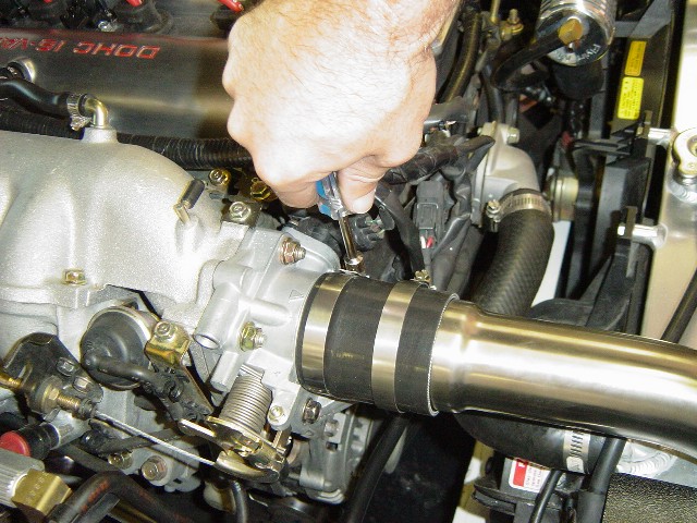
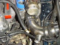
- Spray a little soapy
water onto the hose connection and flange of the throttle body.
Slide the hose connector over the flange of the throttle body.
- Lightly tighten all
of the hose clamps, but don't securely tighten until both Intercooler
pipes are installed as you will need to align the Intercooler pipes
with the radiator shield.
CAUTION: You need to keep
about a 1/4" to 3/8" space between the pipes
and the component that it attaches to for proper flexing. Damage to
the Intercooler could occur from engine torque.
Click
on thumbnail image to see larger image in a new window
|
| 
|
 |
 |
| Photo
11-A: Lower silicone connector intake side |
Photo
11-B: Insert intake pipe into silicone connector |
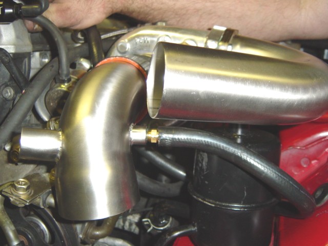
Photo
11-C: Rotate I/C pipe into position |
|
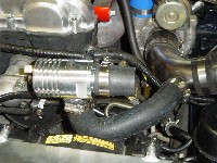
11-2 Installing FM System Turbo Side Intercooler Pipes.
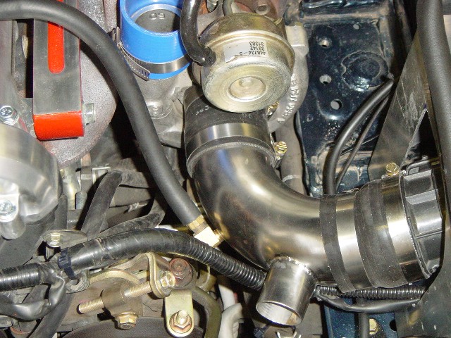
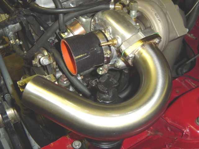
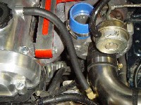
- Install a 2 1/2"
silicone hose to the turbo inlet along with the turbo inlet
pipe. Secure the clamp on the turbo side as shown in Photo 11-D.
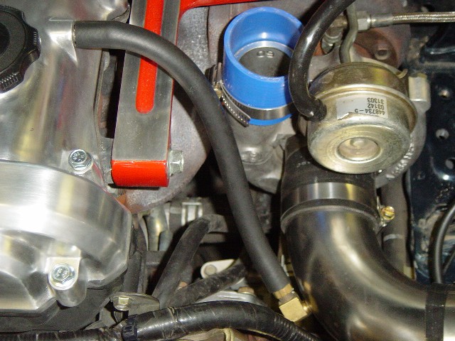
- Install the 3/8"
barb fitting in the turbo inlet pipe for the valve cover
vent hose as shown in Photo 11-E.
- Install the MFS
unit using the 2 1/2" to 2 3/4" transition hose
and secure as shown in Photo 11-D
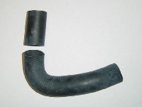
- Using the rubber
hose elbow as shown in Photo 11-F, determine the length
needed to hold the BOV to the turbo outlet pipe, usually this
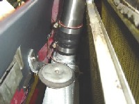
is about 1 3/4" long. Cut the hose on the short length
of the elbow as shown in Photo 11-G. Be sure to fit the unit
to the pipes before cutting.
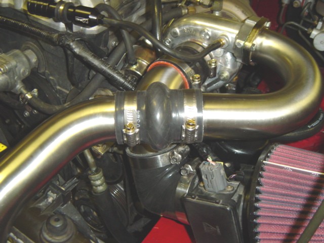
- Install the hump
hose to the Intercooler using the smaller pipe clamps facing
toward the front as shown in Photo 11-H. Slide the hose down
to were the bottom of the hump is at the top of the Intercooler
pipe. Ideally you want the top Intercooler pipe to mount
just above the hump to allow flexing in between. Tighten the
bottom clamp securely. Place another clamp onto the top of the
silicone hose.
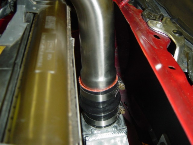
- Install the 2"
silicone hose to the turbo outlet pipe as shown in Photo
11-I. Attach two clamps while securing the bottom clamp only.
- Install the turbo
outlet pipe into the lower connector and into the turbo
outlet. Spraying a little soapy water can help aid the alignment.
Tighten the clamps, but not securely until the final alignment
as shown in Photo 11-I
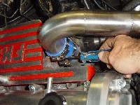
- Install the BOV
hose into the turbo outlet pipe and tighten the clamps,
but not securely tighten until the final alignment as shown
in Photo 11-J.
- Attach a 1/8"
vacuum hose to the BOV and to either the turbo outlet fitting
or the turbo outlet pipe. A 1/8" brass barb fitting is
supplied and if not used a plug is also supplied.
NOTE: After
pipe alignment check all fittings to make sure they are secure.
|
Click
on thumbnail image to see larger image in a new window
|
 |
 |
 |
| Photo
11-D: Turbo intake pipe and connector hoses |
Photo
11-E: Valve cover vent tube in intake pipe |
Photo
11-F: Customer's BOV installed in black hose |
 |
 |
 |
| Photo
11-G: Cut the BOV hose as required on the straight, short end |
Photo
11-H: Install hump hose with clamps toward the front. |
Photo
11-I: Install turbo outlet hose with clamps on turbo |
 |
|
|
| Photo
11-J: Install BOV to the turbo outlet pipe |
|
|
|
11.3 Installing
the BRP System Intake Side Intercooler Pipes
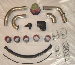 The
BRP turbo Intercooler kit comes with four pipes. The turbo outlet
consist of two pipes separated by a silicone hump hose to add
more flex. The non-intercooled version did not have a proper intake/filter
setup. The TDR kit includes a new intake pipe setup with new air
filter. Some of the early versions came with proper recirculating
BOV, blow-off-valves which you will reuse. If your version did
not have this setup, you will be required to purchase a recirculating
BOV. TDR sells an inexpensive model for $49 or there are other
models such as those from Turbo XS that are available. The
BRP turbo Intercooler kit comes with four pipes. The turbo outlet
consist of two pipes separated by a silicone hump hose to add
more flex. The non-intercooled version did not have a proper intake/filter
setup. The TDR kit includes a new intake pipe setup with new air
filter. Some of the early versions came with proper recirculating
BOV, blow-off-valves which you will reuse. If your version did
not have this setup, you will be required to purchase a recirculating
BOV. TDR sells an inexpensive model for $49 or there are other
models such as those from Turbo XS that are available.
To make fitting of
the silicone hoses to the parts easier, spray a little soapy water
onto the hose connection before installing. The soapy water also
acts as a sealant when it dries.
- To simplify installation
and removal of the silicone hoses on the Intercooler, mount
the clamps so that the tightening screw is on the front side,
as shown in Photo 11-K. This will give you more clearance with
a nut driver (recommended for more torque) or screwdriver.
- Install the hump
hoses onto the Intercooler using the smaller size hose clamps
as shown in Photo 11-K. Slide the hose down so that the bottom
of the hump is at the top of the Intercooler pipe. Ideally
you want the top Intercooler pipe to mount just above the hump
to allow flexing in between. Tighten the bottom clamp securely.
Place another clamp onto the top of the silicone hose. Photo
11-K also shows placement of the factory horn mounted to the
top of the intercooler.
- Install the intake
pipe into the lower connector hose. Take the 2 1/2"
silicone hose and slide it on to the Intercooler pipe at the
top as shown in Photo 11-L.
- Place two larger
clamps onto the pipe with the tightening screws toward the
inside, as shown in Photo 11-L. Holding the assembly, rotate
the intercooler pipe toward the throttle body and line up as
shown.
- Spray a little
soapy water onto the hose connection and flange of the throttle
body. Slide the hose connector over the flange of the throttle
body.
- Lightly tighten
all of the hose clamps, but don't securely tighten until
both Intercooler pipes are installed as you will need to align
the Intercooler pipes with the radiator shield.
- Install the BOV
to the intake pipe using about 1 3/4" of the 1"
silicone hose supplied. Clamp the hose to the intake pipe and
BOV as shown in Photo 11-M.
- Measure and cut
the 1" silicone hose to fit between the BOV and the
turbo intake pipe.
- Attach the 1/8"
vacuum hose to the BOV and intake manifold as shown in Photo
11-M.
CAUTION: You need
to keep about a 1/4" to 3/8" space between
the pipes and the component that it attaches to for proper flexing.
Damage to the Intercooler could occur from engine torque.
11-4 Installing
BRP System Turbo Side Intercooler Pipes.
- Install the 2
1/2" to 2 1/4" transition hose to the turbo inlet.
Secure the clamp on the turbo side as shown in Photo 11-N.
- Install the 3/8"
brass barb fitting for the valve cover vent hose on to the
turbo intake pipe. Attach a 3/8" hose to the fittings as
shown in Photo 11-O and attach to the valve cover vent fitting.
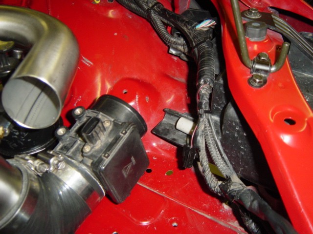
- Clean up the
wiring area where the air filter will be located. You can
clip the holders on the base for the wiring harness and the
hood release cable and bring above the headlight assemble. Tie-Wrap
the relays and harness together. You can push the relays under
the fender area behind the headlight assembly as shown in Photo
11-P.
- Install the 90
deg. silicone elbow to the stainless steel elbow with large
clamps as shown in Photo 11-Q.
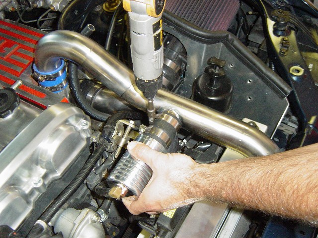
- Install the MFS
to the hose and place so the terminals face upward as shown
in Photo 11-Q. Clamp lightly until all the components are installed.
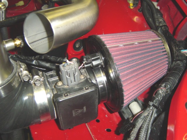
- Install
the air filter with the fitting for the temperature
sensor facing upwards as shown in Photo 11-R. Install the air
temperature and MFS wiring connector. The air filter has a stainless
steel seam that is exposed as shown in Photo 11-R, you can paint
this black with a Sharpie or paint to hide the seam.
- To simplify installation
and removal of the silicone hoses on the Intercooler, mount
the clamps so that the tightening screw are on the front side.
This will give you more clearance with a nut driver (recommended
for more torque) or screw driver.
- Install
the hump hose on
the intercooler to were the bottom of the hump is at the top
of the Intercooler pipe. Ideally you want the top Intercooler
pipe to mount just above the hump to allow flexing in between.
Tighten the bottom clamp securely. Place another clamp onto
the top of the silicone hose.
- Install
the turbo outlet flanged pipe
using the 6 x 25 mm supplied hardware. Use existing flange gasket
or silicone sealer.
NOTE: The turbo
may require clocking or twisting to align the pipes. Use a rubber
mallet or other means if you are not able to simply turn the turbo
housing with force.
- Install
the lower turbo outlet pipe into
the intercooler hose, make sure there is a clamp on the hose.
- Install
the 2" hump hose
on the lower pipe with hose fittings. Test for alignment
and space between the two pipes. Ideally you want about a 1/4"
to 3/8" clearance between the two pipes. Slide the hose
over the turbo outlet pipe and secure as shown in Photo 11-U.
NOTE: Pipe
alignment should be close, but does not have to be exact, the
hump hose can help in some misalignment.
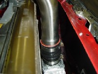
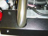
11.5 Installing
the radiator shield temporarily for aligning the Intercooler
pipes before securely tightening the clamps.
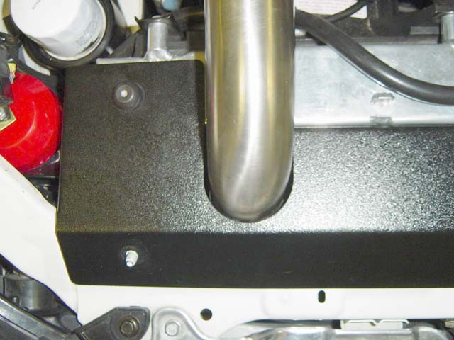
- Take the aluminum
radiator shield and place it on the rubber radiator supports
and the studs on the sub frame, as shown in Photo 11-V. Check
the fit between the shield and the Intercooler pipes to make
sure you have good clearance and are not making contact with
the shield as shown in Photo 11-V.
- Securely tighten
the hose clamps on the engine side to maintain alignment
of the Intercooler pipes. Use a nut driver for more torque.
- Remove the aluminum
radiator shield and securely tighten all the Intercooler
hose clamps.
- Finally attach
the aluminum radiator shield using the two supplied 13mm
Acorn nuts from Package A-2.
|
Click
on thumbnail image to see larger image in a new window
|
| 
|
 |
 |
| Photo
11-V: Check pipe position. Here it is too far to the left. |
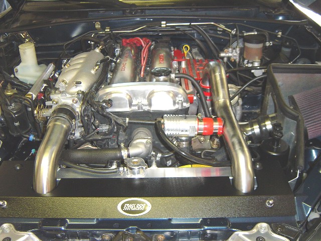
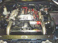
Photo
11-W: Pipe position properly. Repeat for other side and then tighten
down all clamps (upper and then lower). |
Photo
11-X: Finished installation |
|