|
 The
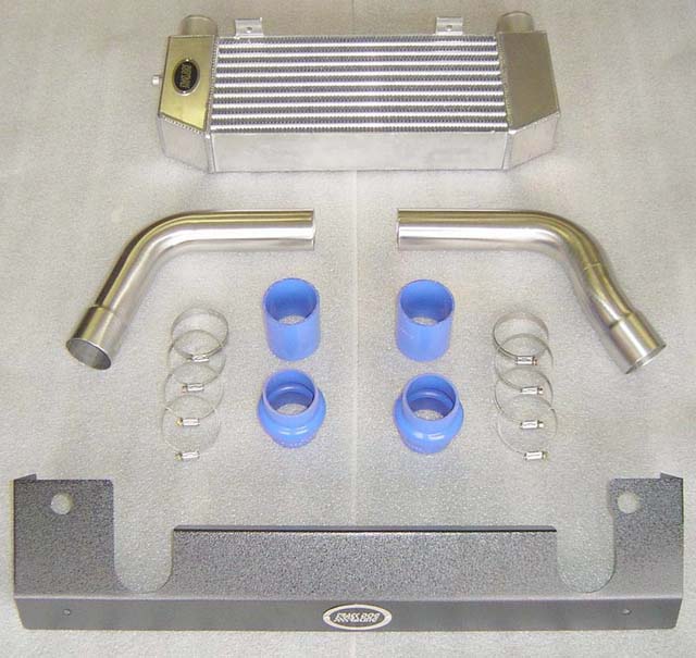
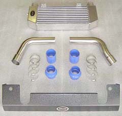
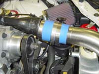
Intercooler pipes are made from 304 stainless steel with a beautiful
brushed finish. The two Intercooler pipes are distinctly different.
The supercharger side pipe has more bends than the intake side pipe
as shown in the photo to the right. There are four silicone hoses and
clamps. The hump hose has the bulge in it to allow more flexing from
the torque of the engine. The hump hoses use the smaller clamps for
mounting and attaching to the Intercooler. The other two transitional
silicone hoses mount on the engine side. Soapy water simplifies
the installation of the silicone hoses when sliding them onto the pipes,
the dummy throttle body and supercharger outlet. To protect the silicone
hoses we specify only liner-type clamps that won't tear the silicone
surfaces and weaken the integrity of the silicone hoses. The
Intercooler pipes are made from 304 stainless steel with a beautiful
brushed finish. The two Intercooler pipes are distinctly different.
The supercharger side pipe has more bends than the intake side pipe
as shown in the photo to the right. There are four silicone hoses and
clamps. The hump hose has the bulge in it to allow more flexing from
the torque of the engine. The hump hoses use the smaller clamps for
mounting and attaching to the Intercooler. The other two transitional
silicone hoses mount on the engine side. Soapy water simplifies
the installation of the silicone hoses when sliding them onto the pipes,
the dummy throttle body and supercharger outlet. To protect the silicone
hoses we specify only liner-type clamps that won't tear the silicone
surfaces and weaken the integrity of the silicone hoses.
Hardware Package
A-2 and F
11-A Installing Intake
Side Pipes
To make fitting of the silicone
hoses to the parts easier, spray a little soap water onto the hose connection
before installing. The soapy water also acts as a sealant when it dries.
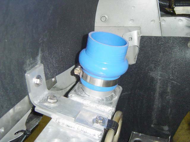
- To simplify installation
and removal of the silicone hoses on the Intercooler, mount the
clamps so that the tightening screw is on the front side, as shown
in Photo 11-A. This will give you more clearance with a nut driver
(recommended for more torque) or screwdriver.
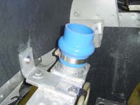
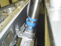
- Install the hump hoses
onto the Intercooler using the smaller size of the two hose clamps
supplied in Package F, as shown in Photo 11-A. Slide the hose down
so that the bottom of the hump is at the top of the Intercooler pipe.
Ideally you want the top Intercooler pipe to mount just above the
hump to allow flexing in between. Tighten the bottom clamp. Place
another clamp onto the top of the silicone hose.
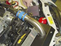
- Install the intake
pipe into the lower connector hose. Take the 2 3/4" to 2
1/2" transition hose and slide it on to the Intercooler pipe
at the top as shown in Photo 11-C.
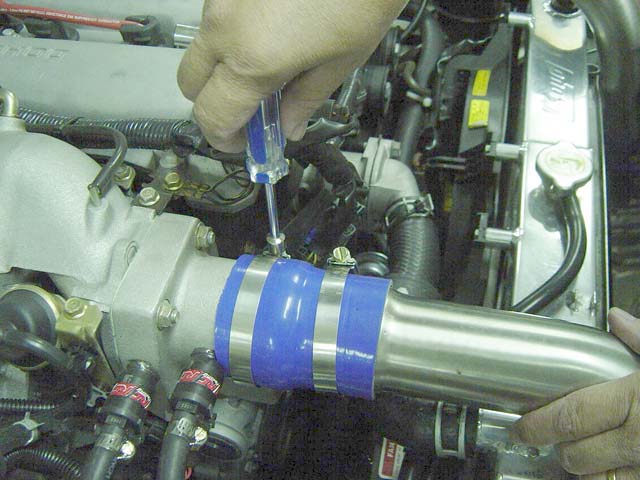
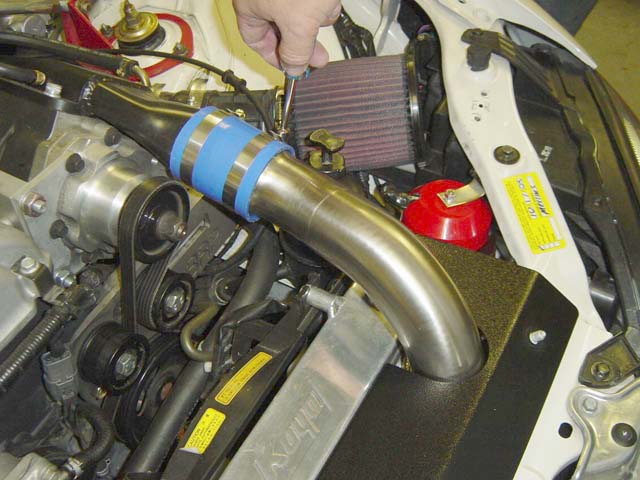
- Place two larger clamps
onto the pipe with the tightening screws toward the fenders, as
shown in Photo 11-D. Holding the assembly, rotate the intercooler
pipe toward the dummy throttle body and line it up as shown.
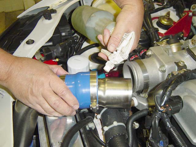
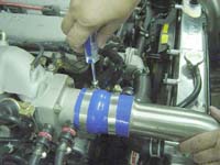
- Spray a little soapy
water onto the hose connection and flange of the dummy throttle
body, as shown in Photo 11-D. Then slide the hose connector over the
flange on the dummy throttle body. This requires some tough pushing
to get over the excessively large lip on the dummy throttle body.
If you have some spare time, remove the dummy throttle body and with
a grinder remove most of the lip to make it more "user-friendly."
- Lightly secure all
hose clamps into position, but don't tighten until both Intercooler
pipes are installed as you will need to align the Intercooler pipes
with the radiator shield.
Click
on thumbnail image to see larger image in a new window
|
| 
|
 |
 |
| Photo
11-A: Lower silicone connector intake side |
Photo
11-B: Insert intake pipe into silicone connector |
Photo
11-C: Rotate I/C pipe into position |
 |
 |
|
| Photo
11-D: Use soapy water here |
Photo
11-E: Slide connector over DTB and secure clamps |
|
|
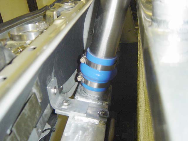
11-2 Installing Supercharger Side Intercooler Pipes.
- To simplify installation
and removal of the silicone hoses on the Intercooler, mount
the clamps so that the tightening screw are on the front side.
This will give you more clearance with a nut driver (recommended
for more torque) or screw driver .
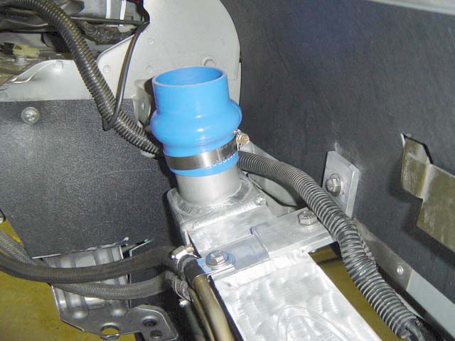
- Install the Hump
hoses to the Intercooler using the smaller of the two pipe
clamps supplied in Package F as shown in Photo 11-F. Slide the
hose down to were the bottom of the hump is at the top of the
Intercooler pipe. Ideally you want the top Intercooler
pipe to mount just above the hump to allow flexing in between.
Tighten the bottom clamp down. Place another clamp onto the
top of the silicone hose.
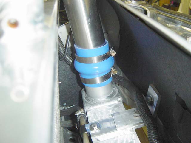
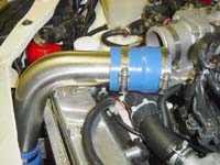
- Install the supercharger
pipe into the lower connector and have the end pointing
inwards. Take a silicone hose and slide it on to the I/C pipe
at the top end. Spraying a little soapy water can help aid the
sliding.
- Place two clamps
onto the pipe as shown in Photo 11-G with the tightening
screws toward the fender. Holding the assembly rotate the I/C
pipe toward the Supercharger and line it up as shown in Photo
11-H
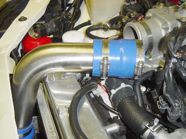
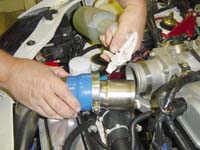
- Spray a little
soapy water onto the hose connection and flange of the Supercharger
as shown in Photo 11-D. Then slide the hose connector over the
flange on the Supercharge. This side is a little easier than
the dummy throttle body, but does requires some pushing to get
it on.
- Lightly secure
all the hose clamps into position, but don't tighten down
until both Intercooler pipes are installed as you will need
to align the I/C pipes with the radiator shield.
|
Click
on thumbnail image to see larger image in a new window
|
 |
 |
 |
| Photo
11-F: Lower silicone connector supercharger side |
Photo
11-G: Rotate Intercooler pipe into position |
Photo
11-H: Align pipe. Use soapy water on connectors to help slide connector
into place. |
 |
|
|
| Photo
11-J: Tighten clamps, but you must be able to move them for
shield fitting (see below). |
|
|
|
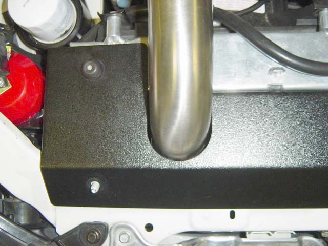
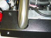
11.3 Installing
the radiator shield temporarily will aid in aligning the Intercooler
pipes before tightening.
- Take the aluminum
radiator shield and place it on the rubber radiator supports
and the studs on the sub frame, as shown in Photo 11-L. Check
the fit between the shield and the Intercooler pipes to make
sure you have good clearance and are not making contact with
the shield as shown in Photo 11-M.
- Securely tighten
the hose clamps on the engine side to maintain alignment
of the Intercooler pipes. Use a nut driver for more torque.
- Remove the aluminum
radiator shield and securely tighten all the Intercooler
hose clamps.
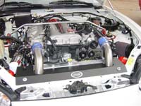
- Finally attach
the aluminum radiator shield using the two supplied 13mm
Acorn nuts from Package A-2 as shown in Photo 11-N.
|
Click
on thumbnail image to see larger image in a new window
|
| 
|
 |
 |
| Photo
11-L: Check pipe position. Here it is too far to the left. |
Photo
11-M: Pipe position properly. Repeat for other side and then tighten
down all clamps (upper and lower). |
Photo
11-N: Finished installation |
|